23 June 2010

Water levels

After the detailed planning, Step 13 was to transfer the sketch plan to foam sheets and start the cutting process.  I adjusted some of the sketch plan once I'd begun to lay it out on the foam boards, tinkering further with the real geography to help create playable spaces on the terrain board. 


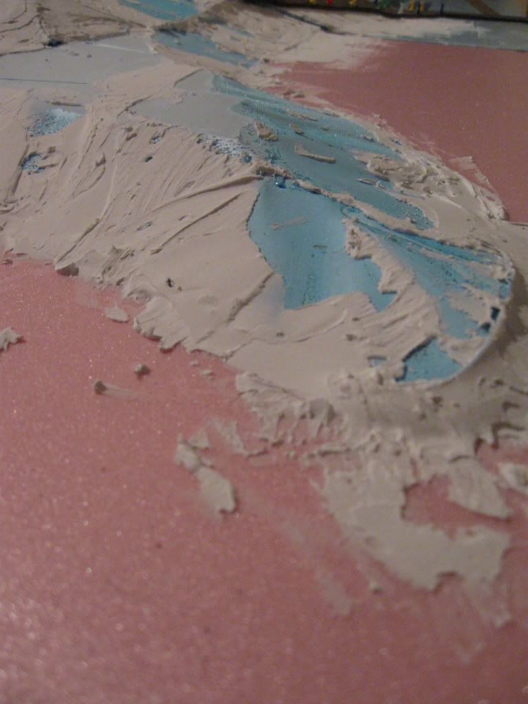
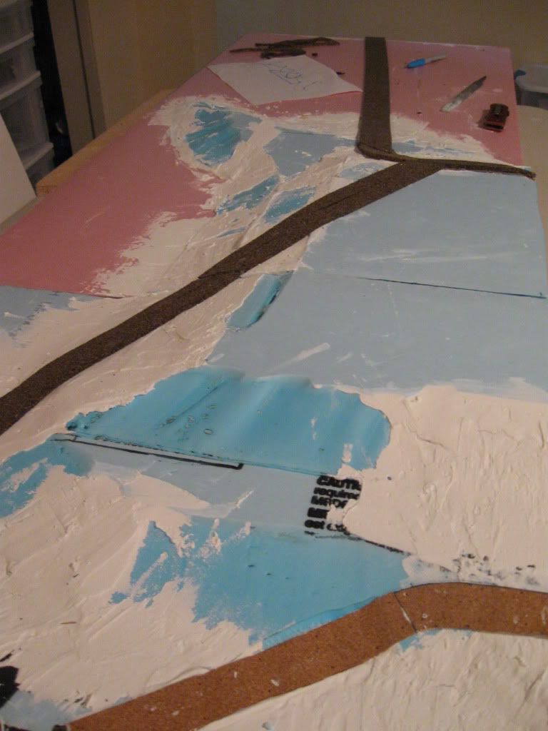
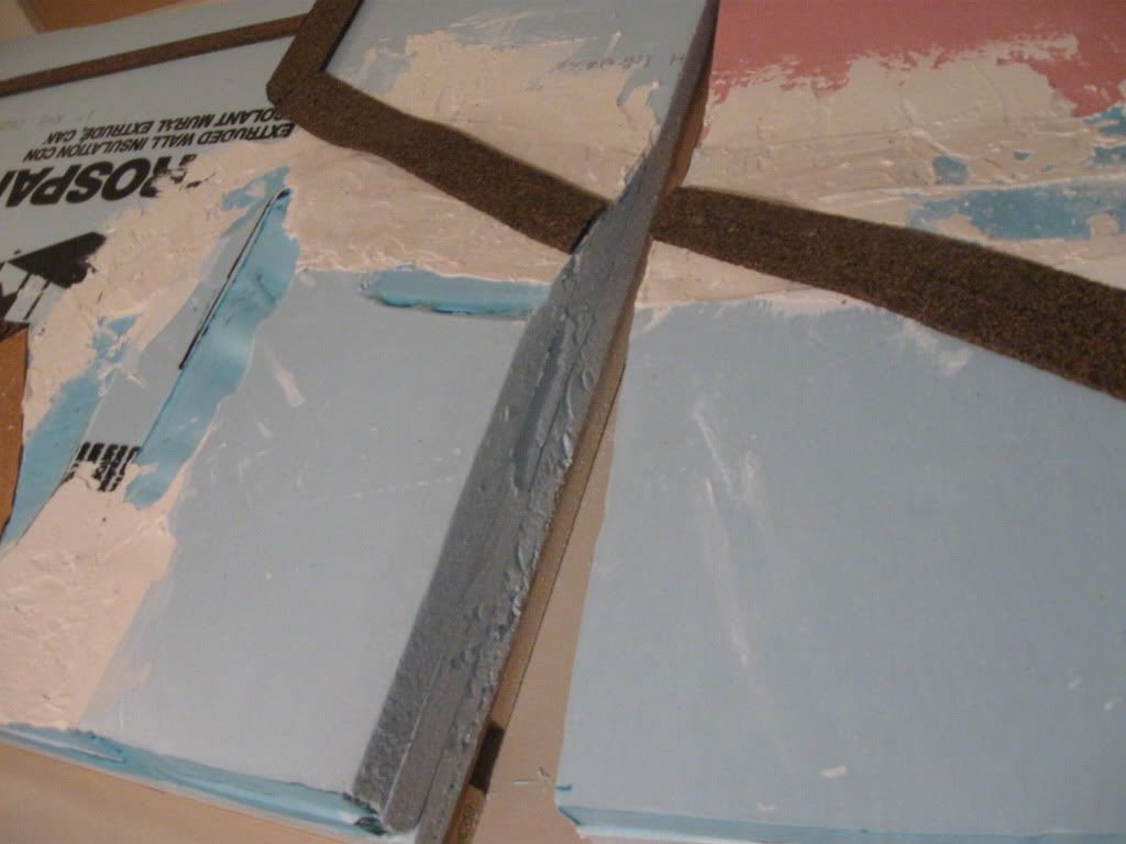
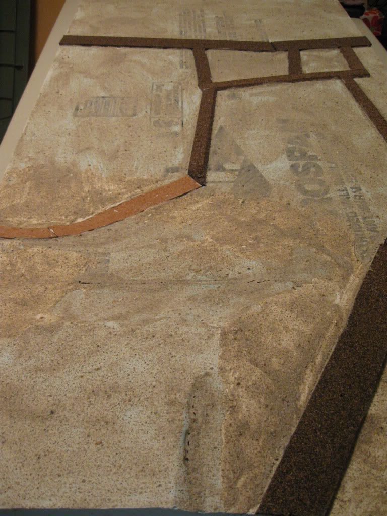
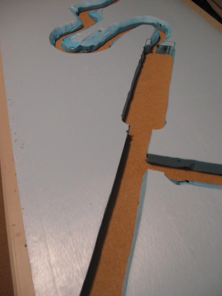
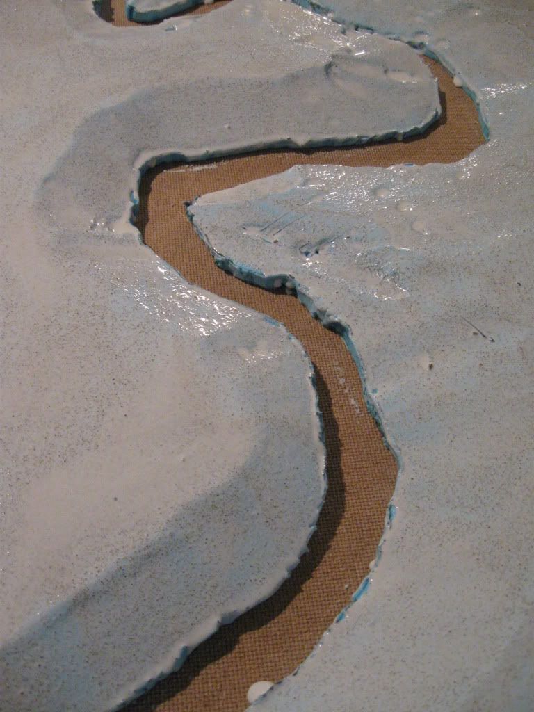
For the cuts, I decided to use straight vertical cuts to form the main shapes.  This meant cutting the sheets apart, as the main flow of the rivers is from corner to opposite corner on the boards.  This is the main reason for changing the orientation for the river boards: having them run north-south in their long direction meant that in other modular arrangements of the boards I can create a longer river about 8' long, while using one river board will always cut a single corner of the table.  Otherwise, the convoluted water courses would have made the boards unplayable in other arrangements.  The other adjustment to my thinking was that I did not want the join between the river boards at the beach end to come right to the edge of the beach - at this stage I also started planning the dunes that would need to project onto the beach tile, incidentally giving more space for fortifications and maneuver.

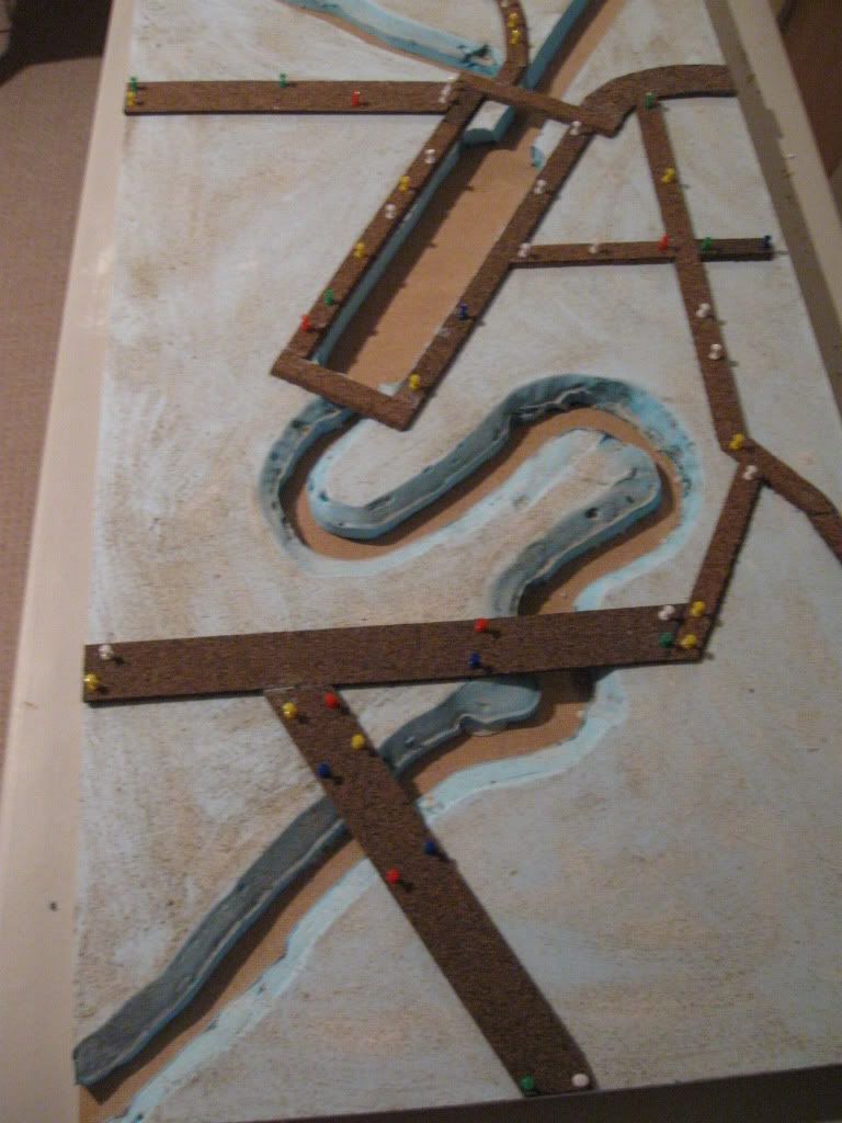
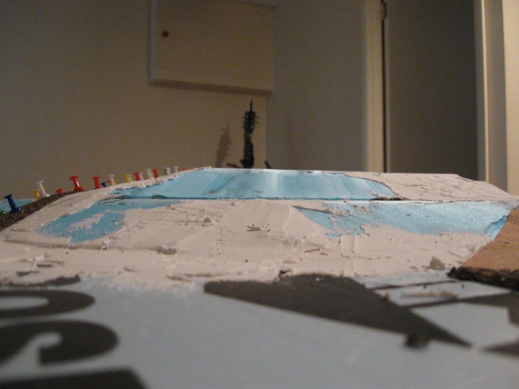
Once the main cuts were made, I then began cutting the slopes/bevels for the riverbanks, trying to maintain long continuous cuts around the curves.  In most areas I cut these riverbanks with a broad, shallow slope to accentuate the various elevations, but in some of the tighter turns I cut the banks steeper.  In play terms, this would allow figures to take some cover on the riverbanks.  Around the fishing harbour, I left the straight cuts in place.  You can see in one of these images that I adjusted the plan again to help with playability and avoid creating too many dead zones where miniatures could not maneuver.


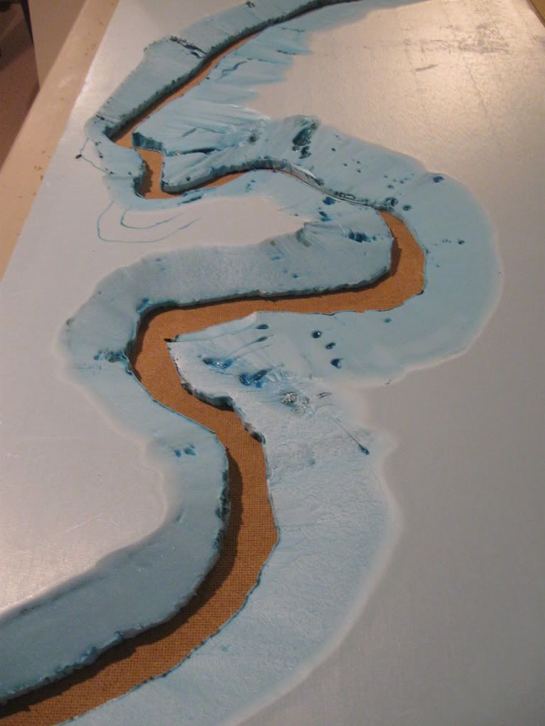
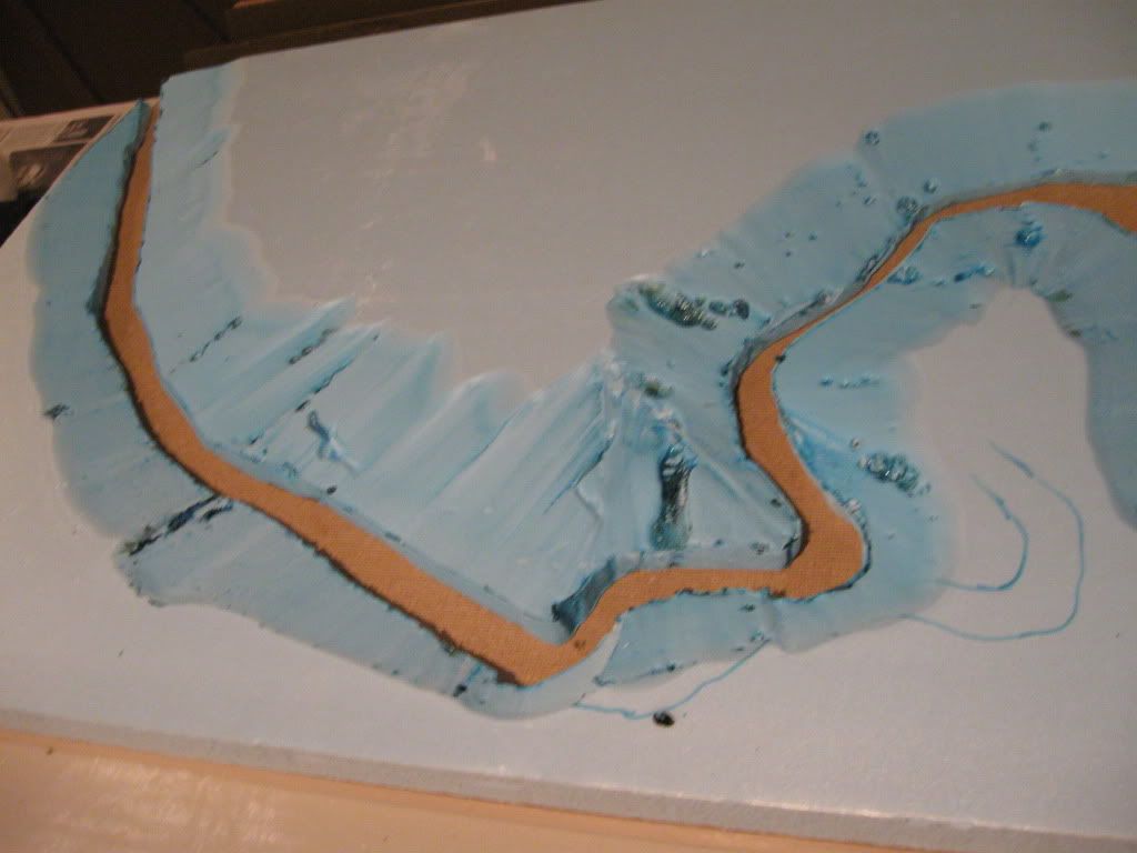
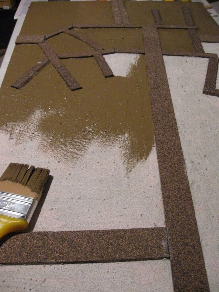
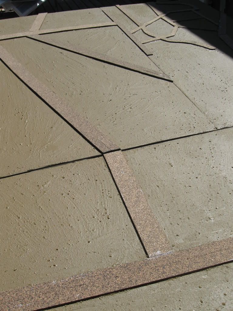
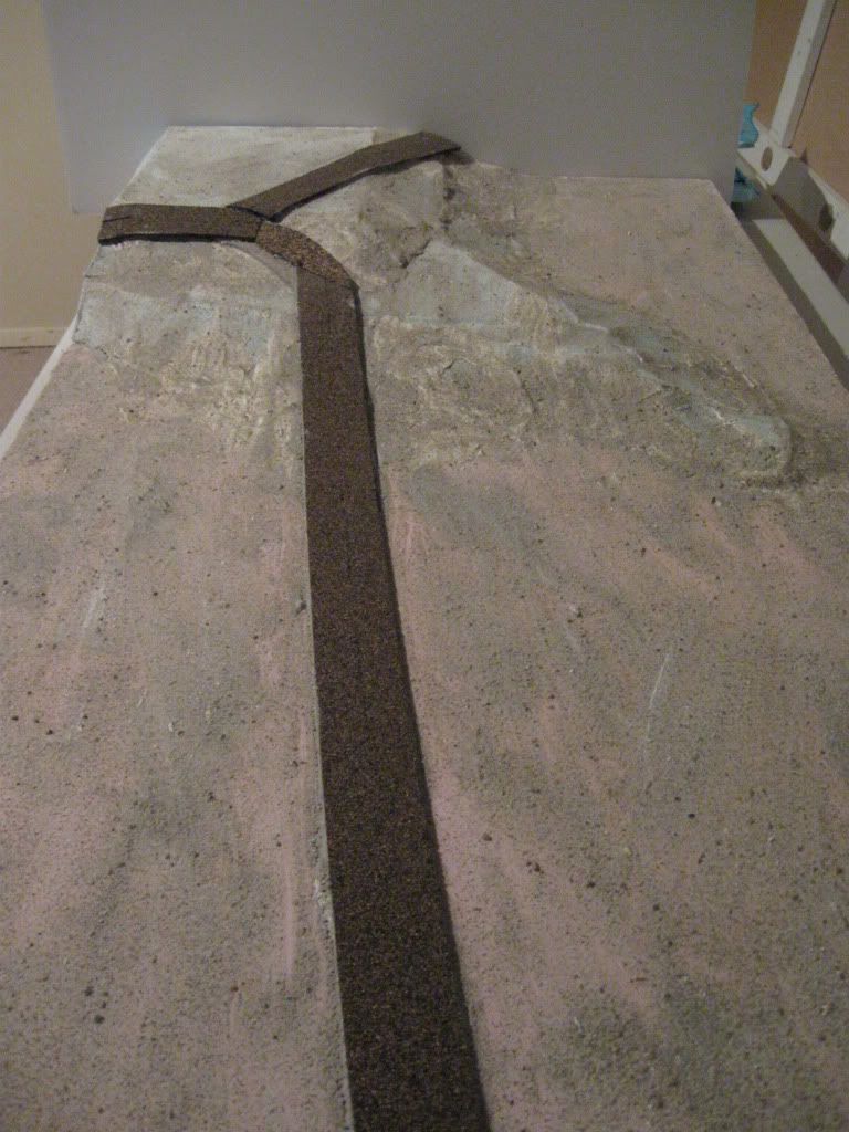
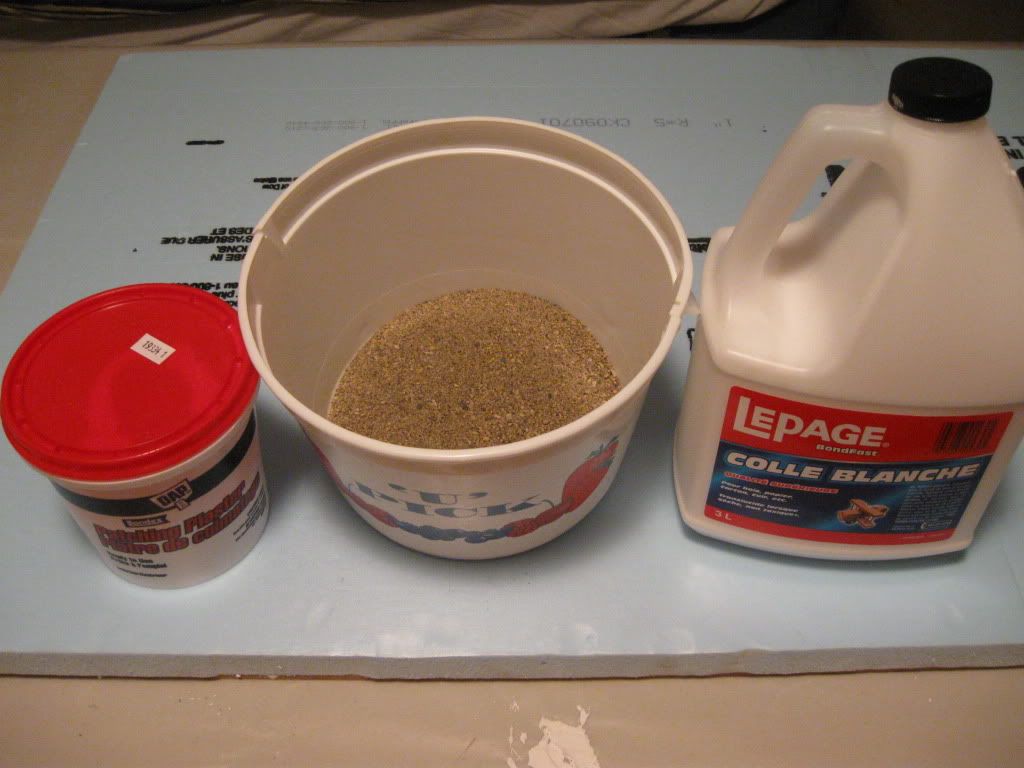
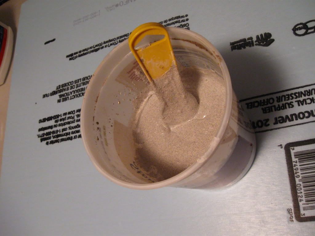
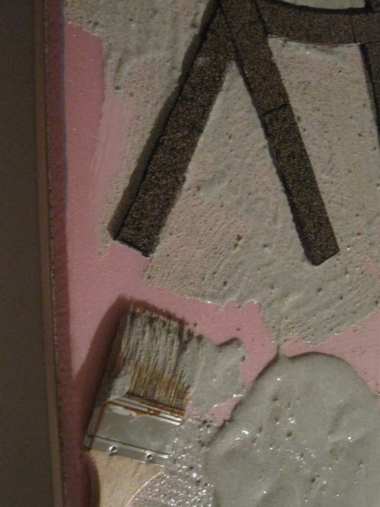
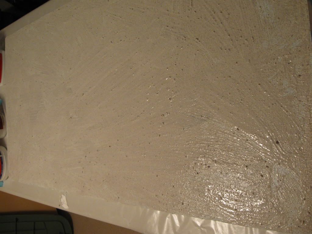
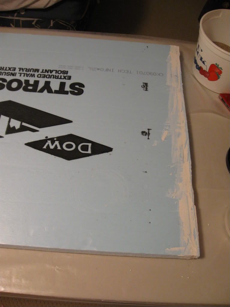
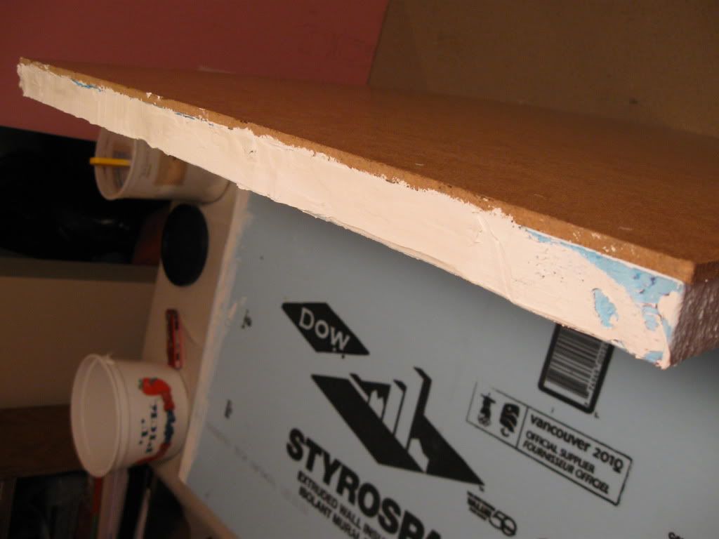
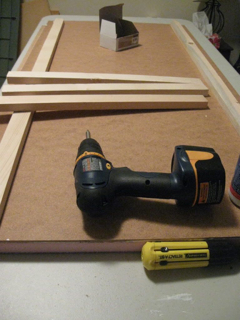
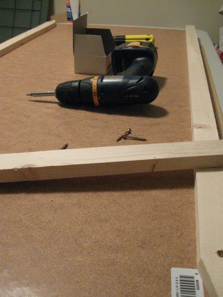
Once the foam pieces were cut, I went back to the beginning and glued these pieces down to the hardboard, then framed these boards underneath.  Then these boards needed plaster to cover some of the irregularities and melted spots from the cutting, followed by texture.


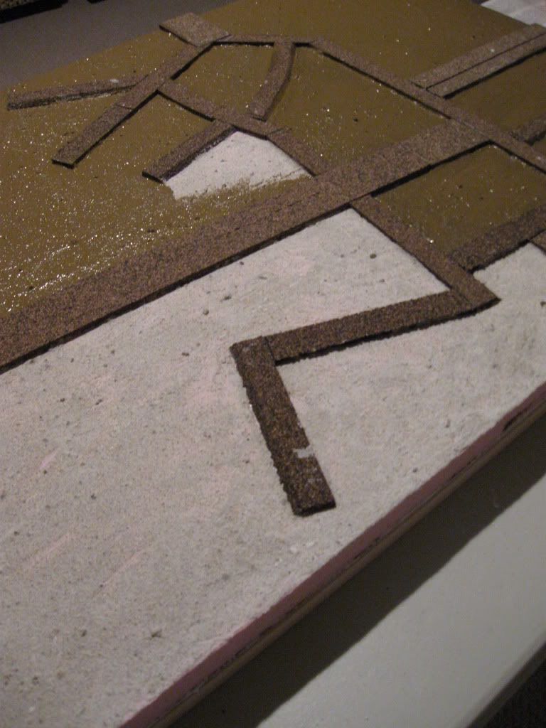
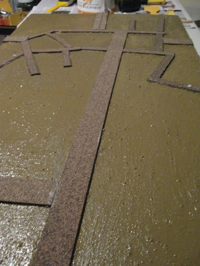
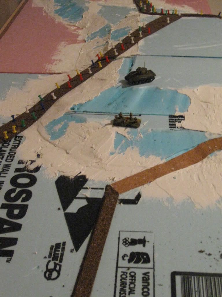
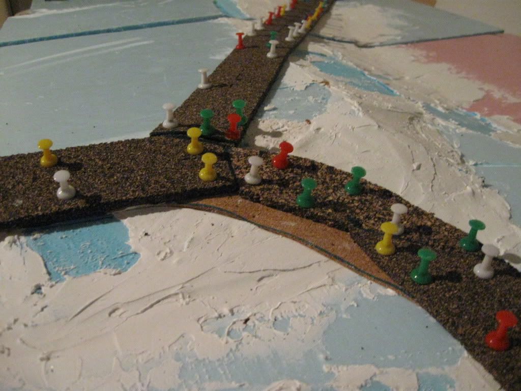
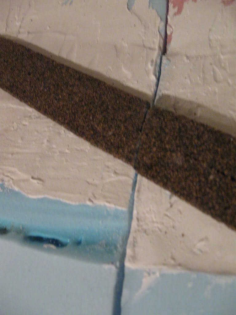
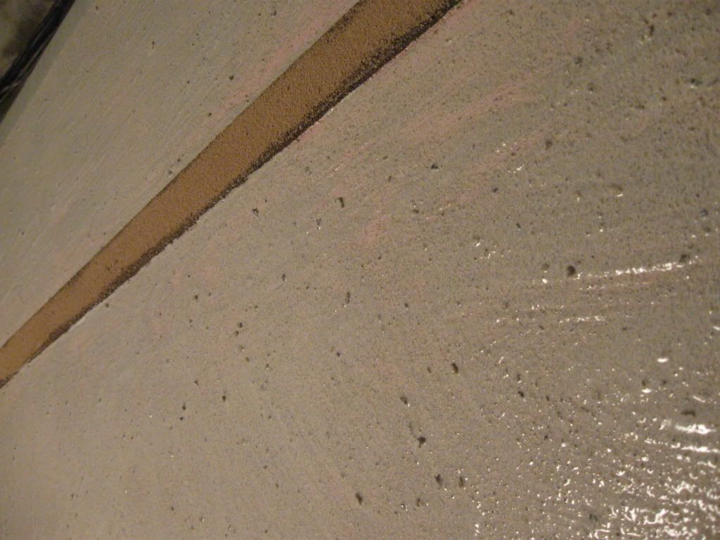
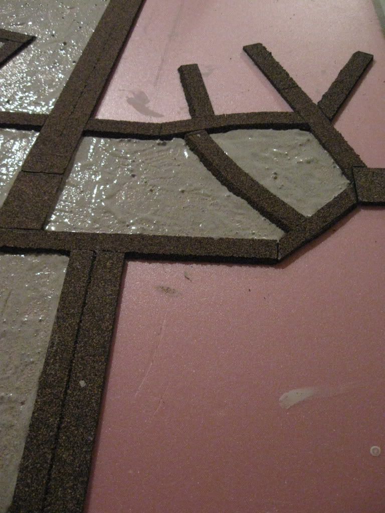
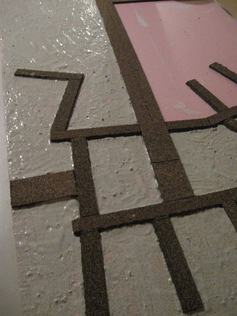
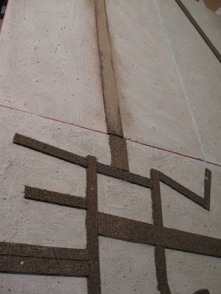
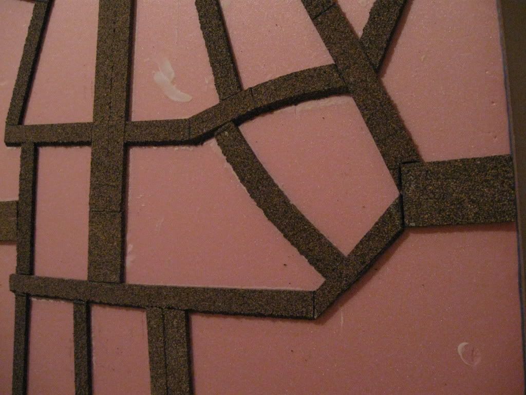
Next came the roads - again a more complex process because of the elevations and bridging.  Most stretches of road needed to be pinned while drying.  One area of doubt I have about the boards to date is the bridging: extending the cork road to bridges gives a stable and permanent structure, but obviously the bridges don't look much like actual bridges.


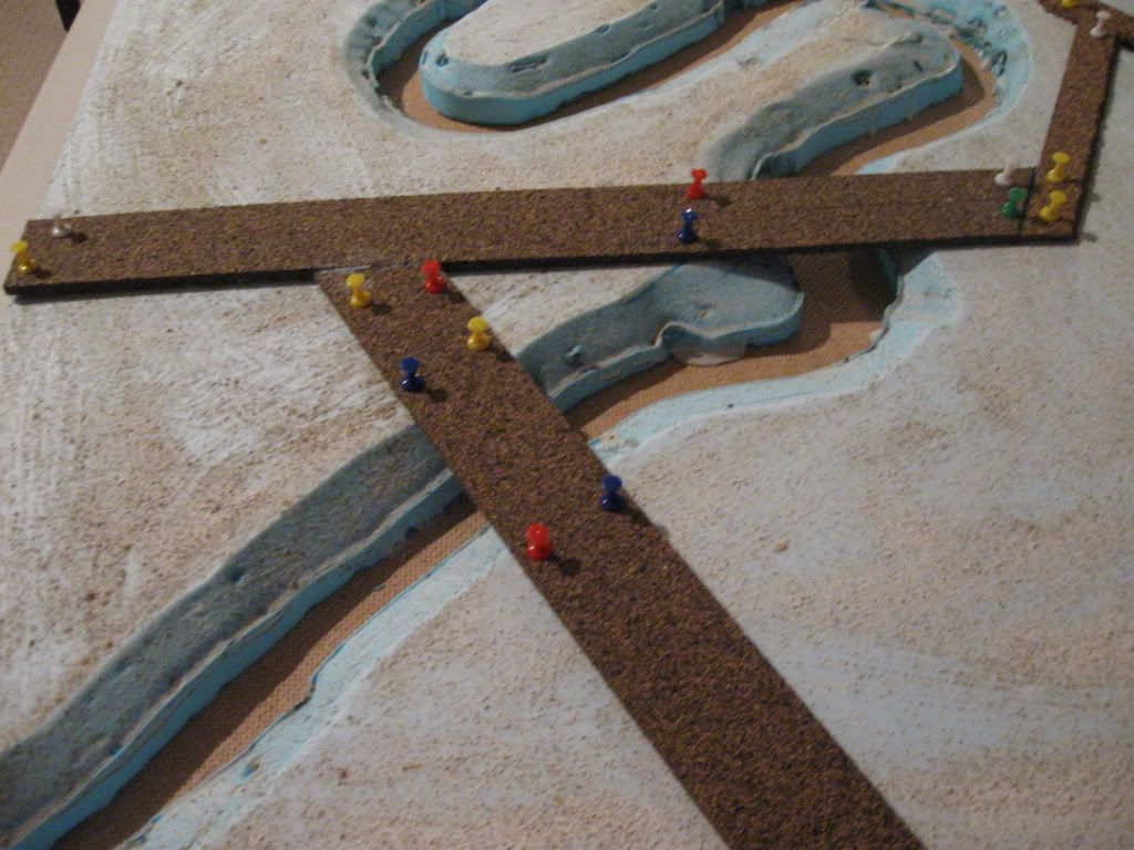
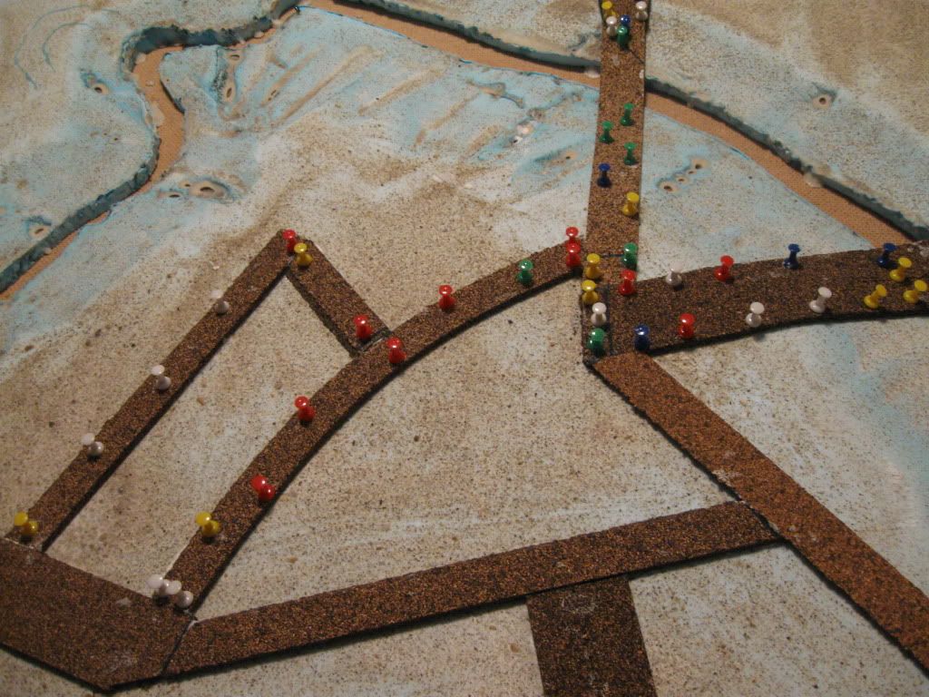
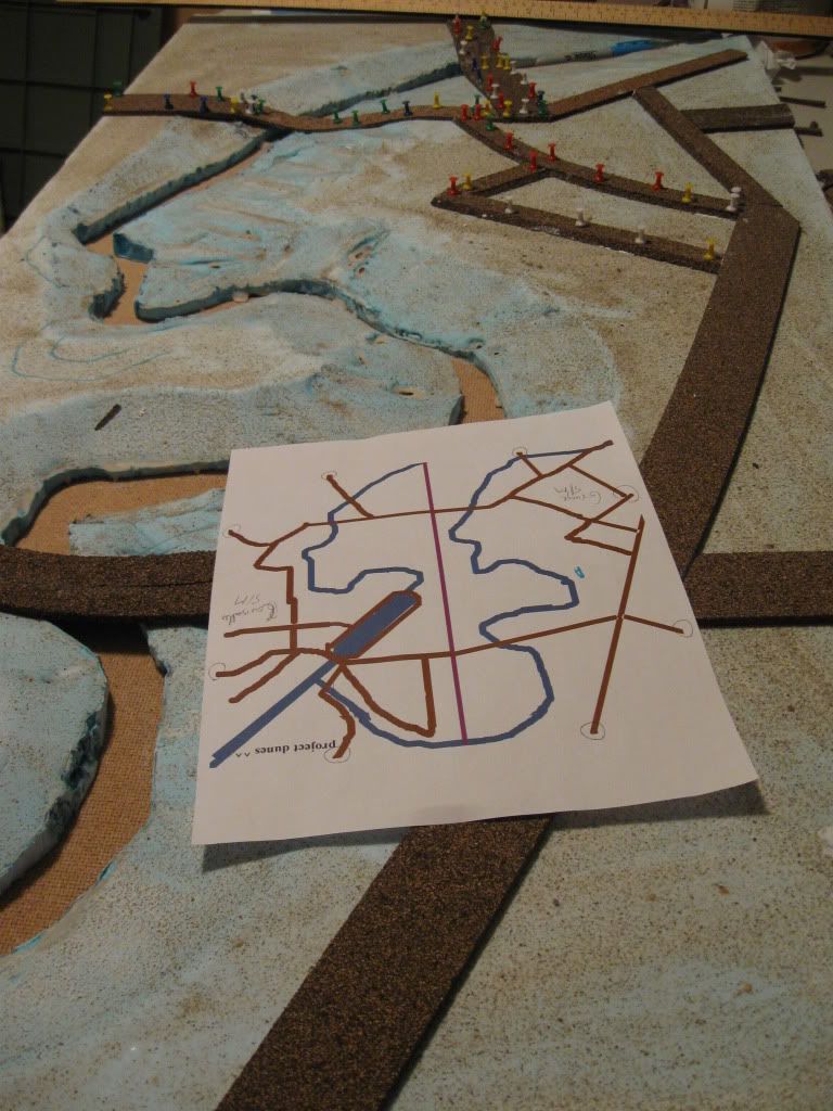
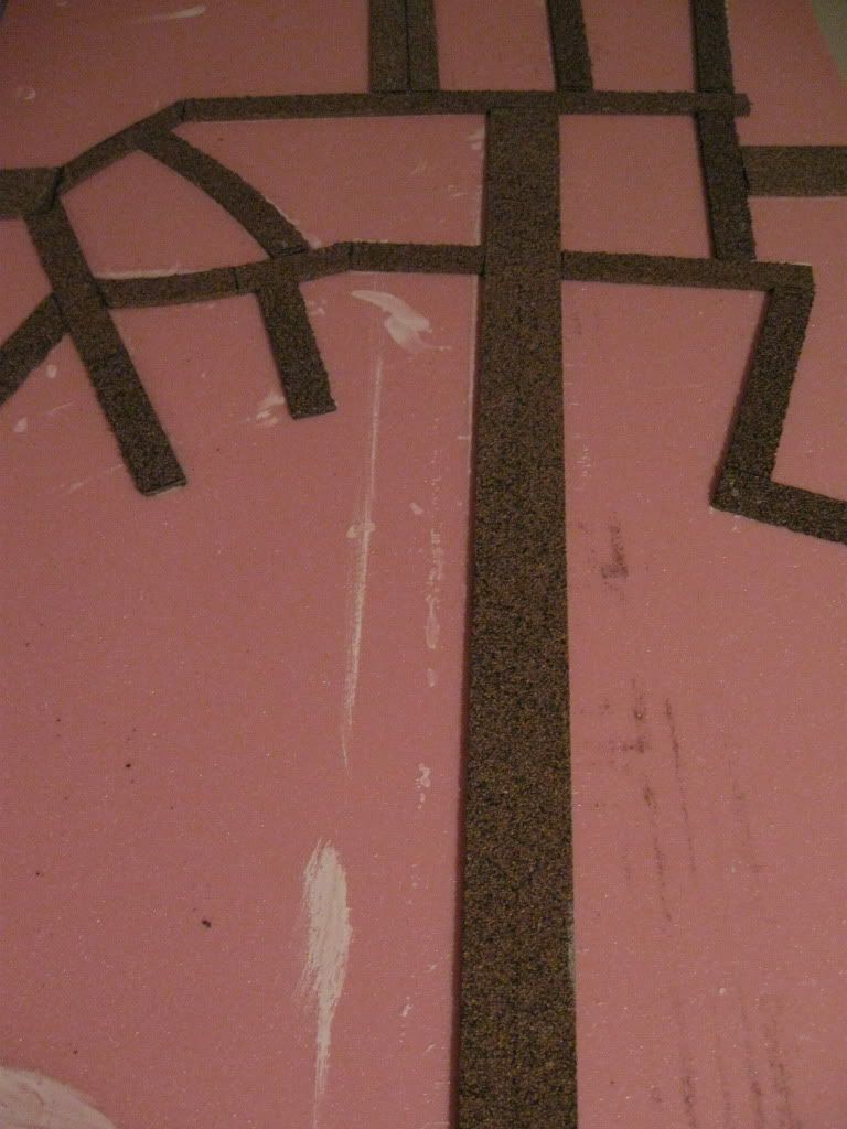
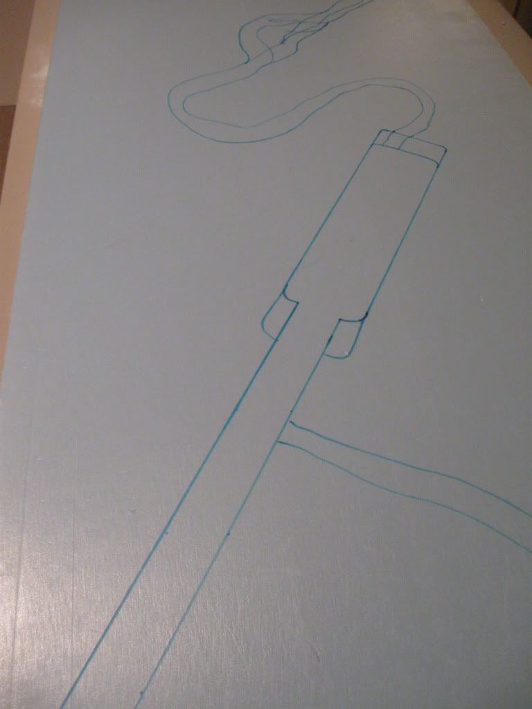
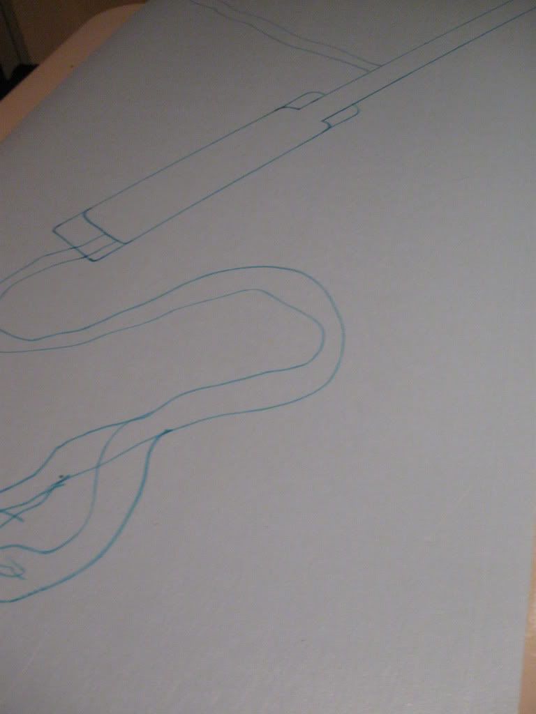
The roads were even more carefully planned because of the riverbanks and the tighter spaces for creating connections.  Below are the sketch plan and the final results for the two boards' roads:


Expanding the Frontage

The coastal defences around the town of Courseulles were particularly challenging for the Canadians, with significant fortifications including bunkers built in front of the town, fortified houses, and connecting tunnels.  The mouth of the river Seulles on the west edge of the town has been heavily altered with the construction of a man-made fishing harbour, with a separate more natural channel for the river winding west of this almost to the coast then turning east back to rejoin the harbour exit.  The complexity of the water courses in the area is visible in this image:

Google Maps: Courseulles-sur-Mer

The Defence Overprint map shows the same situation from the Allied planners' point of view.


The triangle of land immediately west of the harbour mouth and north of the river channel was very heavily fortified with bunkers along the coast, heavy machine-gun positions, observation posts, and an interconnecting tunnel system.  The Royal Winnipeg Rifles were tasked with clearing this western fortified area.  (The Juno Beach Centre museum is now located behind the beach here, with many of the larger fortifications still visible along the coast and dunes.)  The same area is visible in the foreground of a contemporary photo of Canadian troops inspecting a German sand table model of the defences.

So a funny thing happened on the way to our battle.  First, we talked about a larger scale of forces, and in talking about the fortifications it seemed unwise and ahistorical to leave out this section of Juno Beach which presented such a challenge to the Canadian attackers.  I then started to plan to add two further boards to the western end of our table taking it from 12' wide to 16' - but this new development took quite a bit of map work, sketch plans, and a decision to reorient these two boards relative to the rest.  I'll call Step 12 the detailed planning work to add significant water features while maintaining a modular road network - now needing bridges.  More on the reason for the board orientation decision later, but the river boards have been by far the most complex piece of terrain I've built, and even a few weeks after the game the rivers are not fully finished.

21 June 2010

Painting and Counting Costs

After assembling the boards, adding roads and applying texture, Step 10 was to apply the base coat of paint.  I had a 1 gallon/4L can of a military green from a previous project, and I gave each board two coats of this for coverage and durability.


Because this step left the kind of monochromatic ground we're trying to avoid, I followed up by spending some time poring over paint chips to decide on a complementary colour for highlighting.  I wanted a complementary sand- or buff-colour to brighten the highlights and to double as a base colour for some of the later features like sand dunes.

Once I had a colour chosen and mixed, in Step 11 I applied a heavy dry-brush coat.  Dry-brushing is a technique used in miniatures painting where a lighter shade of a base colour is applied after the brush is charged with a little paint and then almost all the paint is wiped from the brush.  Since there is less liquid paint in the brush, the bristles leave only traces of paint over surface features and the paint stays where it's put rather than flowing into gaps.  On miniatures this can be done very delicately in layers with successively lighter colours to create good light-and-shadow effects even with low-relief surface details.  With a heavy dry-brush there's more paint and more pressure, so the paint gets applied to the highest- and mid-relief points (the larger textures in the sand) while leaving the darked undercoat in the "valleys".


With the colours being lighter mixes of the original, this creates a blending effect where it's harder to tell where shadows end and highlights begin, but in this image you can see the light and dark contrast, especially around the larger grains.

A later stage would involve flocking, which ends up covering most of the paint work with artificial vegetation.  So you could probably argue the highlighting is redundant.  But I've found with miniatures and terrain that there's enough show-through to give the work a sense of depth, and the highlighting helps to pull together the painted groundwork and the colour scheme of the flock.

I should make a point about costs here.  Hardboard bases were about C$5 each; foam sheets (making two flat boards or one hill board from one sheet) run about C$16 here; a gallon/4L of PVA glue is about C$25; pre-mixed patching plaster was C$8-9 for a 1 quart /1L tub and I eventually used two of those; cost of sand and hardware was about C$10; and paint ran a bit more than C$25 per gallon / 4L times two, with some left over.  So the average cost per board (considering eight boards eventually) to this stage was:

board and frame: $15
board and frame plus texture: $20
board and frame plus texture and paint: $25.

I'll come back to cost of flocking - but I guess the lesson is that almost half the cost and most of the labour is in the finishing materials.

16 June 2010

Stepping Up

With four boards built, roads added and texture painted on, the next two would be more complex.  The local terrain inland from Juno Beach slopes gradually up from the coastline, and the wargames group had talked about how to create these elevations.  After a long look at Google Earth to get a sense of contours, it was obvious that a large hill would have to spread across two boards.  This would mean aligning the slopes during construction and as part of this connecting the road network at elevation.  Another question of scale needed to be answered too - at game scale, the hills are probably compressed to half the correct height, but otherwise the elevation steps get too narrow and steep.

Step 7 was to cut the basic hill forms from foam sheets, rough-matching the contours from board to board with careful measurement.  The hills were built in steps, including a long projecting ridge as part of the first step.  This irregular shape needed to be cut from two pieces of foam, then glued together and to the base board.


An ant's eye view along the two joining boards shows the steps rising in the distance:


Once each hill shape had been cut, I used the foam knife to carve the slopes.  From experience making other hills, the slope always needs to be more gentle than you'd expect to keep miniatures from sliding down or otherwise being fiddly to place.  These hills were cut with a 1:2 slope (2 or more inches of run for the 1 inch rise of each step).

A couple of quick notes on cutting foam.  I've used a wire-style cutter in the past and never liked the limitation of having to maneuver the U-frame and wire, and they seemed flimsy.  I've switched to a hot knife foam cutter, but temperature control is much trickier with this - too cool and the cuts go very slowly, too hot and very bad things happen (cuts get more aggressive and less controlled, and the surfaces can melt badly or drip melted foam where you don't want it).  With my knife, this means treating the power switch like a throttle and backing off when the cut is moving quickly enough.  Most of the hill here is a second attempt after getting some practice in on a failed first attempt.

Second note: the fumes and smoke from foam insulation are seriously toxic.  I use a half-face filter mask/respirator but twenty minutes of working with foam is enough to leave my eyes burning.  And while making the long, angled cuts for the hill shapes where I shouldn't have been (in a closed basement) I looked up to find an inch-thick cloud of smoke floating below the ceiling.  Use a mask and ventilate well.


To smooth the contours, help with any irregularities in the cuts, and blend the steps and boards together, Step 8 was to use a fair amount of patching plaster.  I then took a large file to the slopes to smooth out the plaster.  In the photo above you can see the plaster in place before filing.

Step 9 was a repeat of laying cork roads, with the added complication of getting these to adhere across the stepped slopes.  This meant easing or levelling some of the grades with a little plaster, and I had to pin these roads much more extensively.


In these images you can see one of the tricks I used to align the boards: I just ran a single long piece of cork road across the two different boards butted against each other as they would fit during play, and pinned and glued it in place there.  Once the glue was completely dry I took my craft knife (yes, the same one I dropped through one of the boards) and cut the two sections apart.


After adding texture to the hills, this left me with eight boards ready for finishing.


One final note about the hill boards: they weigh significantly more than other boards with the added foam and plaster, and their centres of balance are very different with the hill in one corner of each board.  This was an issue for working with them and when setting up.

Adding Texture

The terrain board surfaces need to stand up to dice rolls, things dragged across and dropped on them, and to being moved in and out of vehicles.  And one of the criticisms of wargames tables is that they sometimes resemble pool tables or golf greens - uninterrupted smooth green planes.  Getting around these two issues means strengthening and texturing with some combination of sand and glue.


For Step 6, my base materials were play sand (bought in a 50-lb bag), PVA glue and more patching plaster mixed together to make a slurry.  The sand gives texture and some strength, the plaster gives a spreadable medium and more strength, and the glue binds it all together.  I started out mixing these ingredients in thirds, but my original mixture was too thick, so I ended up adding some water for a 25-25-25-25 mix.


I just mixed a reasonable amount in a bucket.  It goes a long way if it's fluid enough.  Because the sand I used isn't a uniform size, the first batch had some larger pieces mixed in and these added more variety to the surface texture.


Initially I tried to spread the slurry with a palate knife, which worked but was slow and tended to drag texture where I didn't always want it.  Plan B was to thin the mixture a little further and apply it with a cheap paint brush, and that worked much better.  I just poured a pool somewhere central and worked outward from there.  Too large a pool or area and you might lose the workability of the mix.  The most difficult part was working the slurry into the edges of the roadways - leaving a little foam showing to be fixed later during painting.

I did try one board with the slurry added before the roads, which prevented that particular problem but gave me some trouble with getting the cork roads to sit completely flat.


I made a later batch of slurry with the sand sifted better for more uniform texture, and used this mixture mostly in the urban areas where buildings models would have to sit on top of the texture.


Eventually I had six boards fully textured and checked for modular fit:


Once dry, the slurry gave a much more solid surface that was resistant to basic wear and tear, if not to dropping a heavy craft knife straight through one foam sheet all the way to the hardboard.  More patching plaster and slurry.  And yes, I was tempted to stop there and call them desert boards.

15 June 2010

Networking

I struggled with the next step in the process.  Having decided on 4x2 boards and wanting some modularity, which would mean allowing roads, rivers and hills to connect across boards in different configurations, I played around with how to create these connections.  Starting with the roads and laying out different configurations on my regular wargames table, I decided that each board would have up to six connecting points, each one foot from a corner.  This allows two boards to be put side-by-side and a third to be laid across their ends, creating a 4x6 table with each board/panel connected to the others by the road network. Step 4 then was planning out this connection system.  Since not every board has six connectors, the configuration of roads can vary quite a bit on the finished boards.  The 12'x4' table I first set out to build would then have six boards all interconnected by the roads.


Step 5 was to lay in the roads.  For the roadways, I used railroad cork roadbed, some in HO scale, and some in N scale (or split HO pieces) for smaller roads.  After sketching a plan for each board based on the actual Defence Overprint map, I cut the pieces with a hobby knife and glued them down with PVA straight onto the foam.  There were two problem situations.  When the road approached a connecting point at an angle, the road needed its edges shaved to get it down to the same width as the connecting piece.  And where I wanted a curve, I had to pin one end with thumbtacks and force the curve with a series of tacks along its length, then leave the tacks in place until the glue dried.

Cutting and fitting the smaller streets in the urban areas was probably the most time-consuming part of the whole project, since I needed dozens of small pieces in some areas.  On the other hand, I find setting up a road network on a regular wargames table to be time-consuming and not very satisfying unless there are lots of random connectors available - otherwise it ends up as a simple grid.  Eventually this gave me a complex network of roads modelled on the underlying maps, with some adjustment for scale and some distortion to move the real roads into alignment with my board concept - but overall a good fit with the actual roads of Normandy.


My favourite moment in the whole project came much later when Howie from our group recognized the road network in Courseulles because he's just returned from there and had driven on some of the roads I was modelling.

Past Practice 2

Since the end cuts on the foam aren't perfectly even, Step 2 was to take some patching plaster and finish the end to a smooth texture.


Since PVA glue when it dries tends to contract and warp both the foam and hardboard, and to help with elevating the ground above the beach level, Step 3 was to attach a 1" x 2" pine frame underneath the hardboard.  The first attempt was a mess because I ignored advice to pre-drill the holes, splitting the frame in some places and making the fit uneven.  Rewind to cutting some new frame pieces, pre-drilling, and mounting the frame.


Framing pieces run the length of the long edges, with three cross-pieces for lateral support.  Advice was to screw the frame down end to end to take out the warp which was already noticeable, and this worked.


I found that the framing pieces wanted to shift and bend while I worked along the length, but I discovered that putting some heavy pressure with one hand on a spare cross-piece laid across the frame next to the current screw hole kept the frame more stable.  The alignment was very smooth by the end, and I had a stable platform for the first six boards.  I also started to find that the frame was verrey useful as a hand-hold, especially later in the project when surfaces were wet or fragile.